
SDC is a short form of “Synopsys Design Constraint”. SDC is a common format for constraining the design which is supported by almost all Synthesis, PnR and other tools. Generally, timing, power and area constraints of design are provided through the SDC file and this file has extension .sdc.
SDC file syntax is based on TCL format and all commands of sdc file follow the TCL syntax. In sdc file ‘#’ is used to comment a line and ” is used to break the line. SDC file can be generated by the synthesis tool and the same can be used in for PnR.

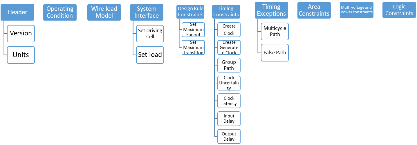
Constraints in the SDC file
Inside the sdc file, some important constraints are as follows.
1. SDC Version:
This statement specifies the version of the SDC file. it could be 2.1, 2.0, 1.9 or more older.
Version 2.1 has introduced in December 2017.
Units of various quantities like time, resistance, capacitance, voltage, current, and power can be specified using set_unit command.
Multiples units can be set using a single set_unit command.
Example:
A. Operating Conditions
B. Wire Load Models
C. System Interface
Let’s discuss some important System Interface constraints in this section.
3. Set driving cells:
specifies the drive characteristics of input or inout ports that are driven by the cells in the technology library. These commands associate a library pin with input ports so that delay calculation can be accurately modelled.
Syntax:
set_driving_load [-lib_cell lib_cell_name] [-library lib_name] [-rise] [-fall] [-min] [-max] [-pin pin_name] [-from_pin from_pin_name] [-dont_scale] [-no_design_rule] [-input_transition_rise rtrans] [-input_transition_fall ftrans] [-multiply_by_facrtor] [-clock clock_name] [-clock_fall] port_list
Example:

4. Set load:
This command sets the load attributes on the specified ports and the nets in the current design. The unit of load value will be the unit of capacitance specified in the unit defined in this file.
D. Design Rule Constraints
In this part basically maximum fanout, maximum and minimum capacitance, and maximum transition time are set
5. Set maximum fanout:
Maximum fanout load is set to a specific input port and/or design
Syntax:
set_max_fanout fanout_value object_list
set_max_fanout 5 [get_ports {port[10]}]
6. Set maximum transition:
Maximum transition time is set by this command which is a design rule and set to clock port or design is set to a specific input port and/or design.
Syntax:
set_max_transition transition_value [-data_path] [-clock_path] object_list
Example:
set_max_transition 2.5 [get_ports IN]
E. Timing Constraints
In this part basically, we set clocks definition, clock group, clock latency, clock uncertainty, clock transition, input delay, output delay, timing derates etc.
7. Create clock:
Syntax:
create_clock [-name clock_name] [clock_sources] [-period value] [-waveform edge_list] [-add] [-comment]
The create_clock command creates a clock object in the current design. This command defines the specified source_objects as a clock source.
Example:

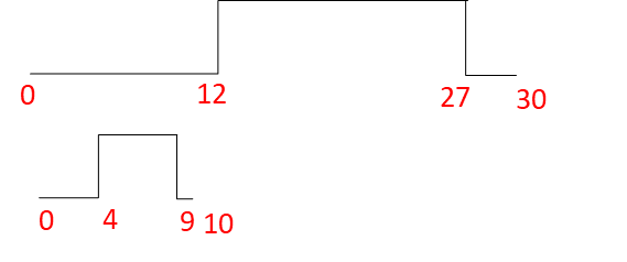
create_clock “u13/z” -name “CLK” -period 30 -waveform {12.0 27.0}
create_clock -name “PH12” -period 10 -waveform {0.0 5.0}
8. Create generated clock:
Syntax:
create_generated_clock [-name clock_name] [-add] source_objects -source master_pin [-master_clock clock] [-divide_by divide_factor | -multiply_by multiply_factor ] [-duty_cycle percent] [-invert] [-preinvert] [-edges edge_list] [-edge_shift edge_shift_list] [-combinational]
The create_generated_clock command creates a generated clock object. A pin or port could be specified for the generated clock object. Generated clock follows the master clock, so whenever the master clock changes generated clock will change automatically. A generated clock can be created as a frequency-divided clock, a frequency multiplied clock, an edge divided clock or an inverted clock.
The above example will generate a clock which is derived from the original clock named CLK. The generated clock will have a frequency 3 times of the original clock and time period will be one-third of the original (15ns –> 5ns).
9. Group path:
Syntax:
group_path [-weight weight_value] [-critical_range range_value] -default | -name group_name [-from from_list | -rise_from rise_from_list | -fall_from fall_from_list] [-through trough_list | -rise_through rise_through_list -fall_through fall_through_list] [-to to_list | -rise_to rise_to_list | -fall_to fall_to_list] [-comment comment_string] [-priority priority_level]
Groups are a set of paths or endpoints for the cost function calculations. The group enables us to specify a set of paths to optimize even though there may be a larger violation in other groups. When endpoints have been specified all paths leading to those end paths are grouped.
Example:
group_path -name “group1” -weight 2.0 -to {CLK1A CLK1B}group_path -name GROUP1 -from [get_ports ABC/in3] -to [get-ports FF1/D]
10. Clock uncertainty:
Syntax:
After defining the clock, to take care of variance in the clock network clock uncertainty added. Clock uncertainty adds some margin of error into the system to account for variance in the clock network caused by non-ideality of clock network and clock source itself.Above specified command can specify either inter-clock uncertainty or simple uncertainty. It sets uncertainty to the worst skew expected to the endpoints or between the clock domains.
Example:

set_clock_uncertainty -setup 0.5 [get_clocks clk1]set_clock_uncertainty -hold 0.2 [get_clocks clk1]
Clock uncertainty can also be added for rise and fall time of the clock as below.
set_clock_uncertainty -min_rise 0.12 [get_clocks clk1]
set_clock_uncertainty -min_fall 0.12 [get_clocks clk1]
11. Clock latency:
Syntax:
Clock latency specifies the amount of delay for a clock signal reaching to the clock pin of a sequential element from the clock source pin. There are two types of clock latency one is network latency (default) and the other is source latency (by using the -source option)
Example:
set_clock_latency 2.35 [get_pins ABC/XYZ/CP]
12. Input delay:
Syntax:
Input delay defines the time requirements of an input port with respect to clock edge. Input ports are assumed to have zero input delay if it is not specified. The delay value to be specified is the delay between the start point and the object on which set_input_delay is being set relative to the clock edge.
set_input_delay -max 1.35 -clock clk1 {ain bin}
13. Output delay:
Syntax:
set_output_delay delay_value [-reference_pin pin_port_name] [-clock clock_name] [ -clock_fall] [-level_sensitive] [-network_latency_included] [-source-latency_included] [-rise] [-fall] [-min] [-max] [-add_delay] [-group_path group_name] port_pin_list
set_output_delay command sets output delay requirements on an output port with respect to the clock edge. Output ports are assumed to have zero output delay if it is not specified.
Example:
set_output_delay 1.7 -clock [get_clocks CLK1] [all_outputs]
Above command will set output delay 1.7 unit to all output ports with respect to the positive edge (default edge) of the CLK1.
set_output_delay -max 1.4 -clock {CLK} [get_ports {Y}]
set_output_delay -min 1.0 -clock {CLK} [get_ports {Y}]
In above command -max value refers to the longest path and -min value refers to the shortest path. If no -max or -min value is specified, maximum and mimum output delays are assumed to be equal.
E. Timing Exceptions
In this part, some of the important constraints like false paths, multicycle paths, maximum delay and minimum delay are defined.
14. Multicycle paths:
Syntax:
A multicycle path is an exception of the default single-cycle timing requirement path. In a multicycle path, signal requires more than one single clock cycle to propagate from the start point to the endpoint of the path. This command specifies the number of cycles the data path must have for setup or hold check. The following command will set a constraint of two cycles path from source point A to endpoint B.
Example:
We can add a -through point between source and endpoint and also we can set multicycle path to all paths my mentioning only source or only endpoint.
Syntax:
set_false_path [-rise] [-fall] [-setup] [-hold] [-from from_list | -rise_from rise_from_list | -fall_from fall_from_list] [-through through_list] [-rise_through rise_through_list] [-fall_through fall-through_list] [-to to_list | -rise_to rise_to_list | -fall_to fall_to_list] [-reset_path]
A false path is a path that can not propagate a signal. For example, a path that is never activated by any combination of inputs is a false path. False paths should be disabled for timing analysis. The SDC command set_false_path is used to define the false paths. False paths will be excluded for timing analysis.
Example:
set_false_path -from U1/G -to U1/D
set_false_path -from {ff12} -to {ff34}
Summary:
This article has described 15 most important constraints in SDC file. There are many more constraints for a complex design. Here is the summary of all discussed constraints.
1. SDC Version
2. Units
System Interface
3. Set driving cells
4. Set load
Design rule constraints
5. Set maximum fanout
6. Set maximum Transition
Timing constraints
7. Create Clock
8. Create Generated Clock
9. Group Path
10. Clock Uncertainty
11. Clock Latency
12. Input Delay
13. Output Delay
Timing Exception
14. Multicycle Path
15. False Path
Thank you!
you have given the same info for input delay and output delay
Thanks Veeralakshmi for your catch.
Same has been corrected now.
Hi how can I constrain inputs/outputs of bus interfaces ?
You can set set_input_delay or set_output_delay.
If we don't fix false paths, why they exist in the design ?
wl
SDC means Standard Design Constraints or Synthesis Design Constraints Right?
can you check it once…
create_clock “u13/z” -name “CLK” -period 30 -waveform {12.0 27.0}
Here in above command “u13/z” represents what??