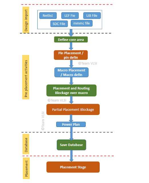
In a broader sense, PnR (Place and Route) stage in physical design is basically Placement and Routing of all the instances present in the netlist in a defined core area in such a way that it should meet design rules and timing requirements. But before starting the actual automatic placement of instances by the PnR tool, there are certain activities which must be done prior to placement and those are called pre-placement activities. In this article, we will discuss some important pre-placement activities.
 |
| Pre-placement activities in PnR |
Major pre-placement activities:
- Pin placement
- Macro placement
- Halo and routing blockage
- Power plan
- Boundary cell/End cap cell placement
- Well tap cell placement
- Partial placement blockage /Density screen creation
Here we will discuss these activities in details in order as they needed to be performed.
Pin placement:
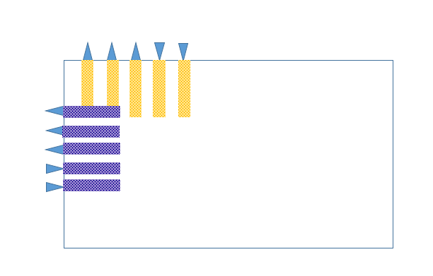
In block-level PnR, input-output pins location are generally decided by the full-chip owner and the pin def is given to block owners. But some times pin location are not fixed at the top level and meanwhile block owner need to place them as per their convenience.
Pin list
Metal layer
Pin widthPin depthSide/edgeSpread / Distance between two pins
 |
| Pin placement in PnR |
Pins location could be either on edge of core or inside the core also. In case of pin def is available, we just need to defIn the pin.def file. In Innovus we can defIn the pin def file as bellow.
defIn <pin.def>
Once all pins are placed, we can check that. In innovus we have a command.
checkPinAssignment
The above command will give the total number of pins, the number of legal/illegal pins, the number of placed/unplaced pins.
Sometimes some i/o pins might have short with the PG structure, We can verify those shorts using following innovus command.
verify_PG_short -no_routing_blkg -no_cell_blkg
In case there are some shorts, we can fix those using following innovus command.
editPin -pin <pin name> -fixOverlap
Once all the pins are placed, we can defOut pins in a file for future use.
selectPin * ; Or selectPin [dbGet top.terms]
defOut -selected <file_name>
Macro Placement:
Macro placement is a major step of the floorplan and the QoR (quality of result) of PnR is strongly dependent on the macro placement. A good macro placement requires thorough analysis of data flow in the block.
A bad floorplan could result in congestion and bad internal timings. There are some steps which must be followed especially in a macro dominating block. A detail discussion on macro placement strategy is explained in this article (will be linked soon).
Halo and Routing blockage:
Macros having high pins count near the edges generally and if the standard cell placement is high there, it could lead congestion. To avaoid this congestion we neet to put halo around the macro. (Halo is explained here – will be linked soon). The macro design needs more metal layers than normal standard cell and its pins are available in higher metal layers than the standard cells. So we need to put routing blockage for the layers which are used inside the macro. The power rails are blocked over the macros and power is delivered to the macros directly from power stripes.
Power Plan:
Boundary cell placement:
Well tap cell placement:
To get tap the psub to VSS and the nwell to VDD in order to avoid the latch-up issue in the design we need to place well tap cells at regular intervals in the core area. A detail discussion on well tap cells and its placement has been discussed in this article.
