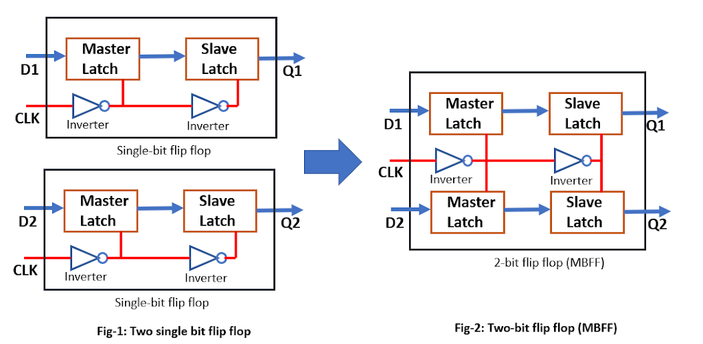
In modern ASIC design use of multi-bit flip flops (MBFF) has increased due to its various promising advantages of MBFF over single-bit flip flop (SBFF). Traditionally we study only a single-bit flip flop in our academics. So it becomes important to understand the design of multi-bit flip-flops, how it works, and what are the advantages/disadvantages of multi-bit flip-flops over single-bit flip-flops.
Why Multi-bit Flip Flops?
Multi-bit flip flop has many advantages due to its architecture over the single-bit flip flop. There are many recent research publications also which show these facts with proper statics. We also witness these advantages while place and route (PnR) implementation. Here I would like to explain the basic facts of MBFF in a simple way without any detailed statics. The exact statics can be referred from any recent research publications. The main advantages of multi-bit flip flop are as follows and that’s why MBFF is used widely now a day.
- Area reduction
- Power reduction (promising for low power designs)
- Better clock skew control
- Timing improvement
So we can say that it improves the area, power, and timing. The reason for these advantages will be explained in the next section.
Multi-bit Flip Flop Architecture:
All the advantages of multi-bit flip-flops are due to their architecture. A single-bit FF and a 2-bit MBFF schematic have shown in the figure-1. A similar architecture can imagine for higher bit MBFF also.
| Figure -1: Multi-Bit Flip Flop |
One can notice that the inverter count reduces when we use the multi-bit flip flop as compare to the single-bit flip flop. The effect of this reduction is more visible when we use bigger MBFF. A comparison of inverter count in SBFF and MBFF has shown in figure-2.
| Figure-2: Number of Inverters used in SBFF and MBFF |
Instead of 16 inverters inside 8 single-bit flip flops, there are only 2 inverters used inside a 16-bit flip flop. A schematic of 8-bit MBFF has shown in figure-3.
| Figure-3: 8-bit MBFF |
As the number of inverters reduced in the case of MBFF, it saves the clock power and area. There is no change in the operation of flops after MBFF conversion. Now let’s discuss the mechanism of how PnR tools convert the SBFFs into MBFFs.
MBFF conversion:
| Figure-5: Placement of MBFF after conversion |
Figures 4 and 5, show how the conversion of SBFF into MBFF. Figure-4 is showing the scenario before MBFF conversion is done and figure-5 shows the scenario after MBFF conversion. In figure-5, we can see that instead of 8 different SBFF only one 8-bit MBFF is used. So MBFF is generally bigger in size and having multi-row height standard cell.
PnR tools have algorithms to convert SBFF into MBFF. The tool picks the equivalent MBFF available in the standard cell library and performs the conversion with respect to the user input provided for conversion. This conversion happens in the placement stage.
If we talk about the Cadence Innovus tool, we have a command
setOptMode -multiBitFlopOpt true
Which enables PnR tools for multibit flop conversion. By default, this conversion is disabled in the tool. There are many such commands in the tool which can be explored further.
Thanks.

