
Well tap cells (or Tap cells) are used to prevent the latch-up issue in the CMOS design. Well tap cells connect the nwell to VDD and p-substrate to VSS in order to prevent the latch-up issue. There is no logical function in well tap cell rather than proving a taping to nwell and p-substrate therefore well tap cell is called a physical-only cell. In this article, we will discuss the structure of well tap cell, the requirement of well tap cell and how to place them in the physical design flow.
Well Tap Cell:
Well tap cells have no logical functions, it has only two connections.
- nwell to the power supply (VDD)
- p-substrate to the ground (VSS)
A typical structure of well tap layout has shown in figure-1. Well tap cell has no input and output pins, therefore it is called a physical-only cell.
 |
| Figure-1: Layout of well tap cell |
Why Well Tap Cell:
Early days there was no concept of well tap cell, Standard cells were designed in such a way that each standard cell had nwell to VDD and p-substrate to VSS connection within the standard cell. But such a standard cell design had consumed more area and to save the area, later a concept of Tapless cell has evolved. In a tapless cell, there are no well taping inside the standard cell, well taping is provided by a separate standard cell which is called a well tap cell. So well tap cell is a part of a tapless standard cell library. Figure-2 shows the structure of a traditional standard cell and a tapless standard cell.
 |
| Figure-2: Traditional and Tapless standard cell structure |
Well tap cells are used to prevent the latch-up issue in design. how it prevent, has been explained in the article “latch-up prevention in CMOS” in this blog.
Placement of Well Tap Cells:
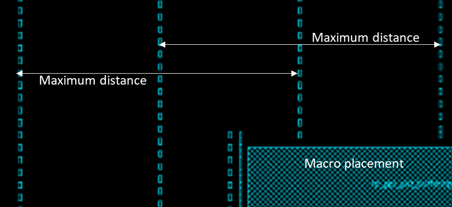
Well tap cells are placed after the macro placement and power rail creation. This stage is called the pre-placement stage. Well tap cells are placed in a regular interval in each row of placement. The maximum distance between the well tap cells must be as per the DRC rule of that particular technology library. A typical placement of well tap cells is shown in figure-3.
 |
| Figure-3: Well tap cell placement |
Well tap cells are generally placed in a straight column in the alternate row as shown in figure and such a pattern is called checkerboard pattern to provide maximum coverage for well tap. If a macro comes in the path of vertical columns, then the placement of vertical column shifted alongside macro as shown in the figure.
This placement is performed using the PnR tool command. For ICC and Innovus tool following command have used to place the well tap cells.
For Innovus tool:
set_well_tap_mode -rule <> -bottom_tap_cell <cellName> -top_cell_name <cellName> -cell <>
addWellTap -cell <cellName> -cellInterval <maxGap> -prefix <prefixName> -checkerBoard -fixedGap
verifyWellTap -report <reportName>
For more details refer UG of Innovus tool.
For ICC tool:
add_tap_cell_array –ignore_soft_blockage true –master_cell_name $tapCell–distance $tapPitch –connect_power_name VDD –connect_ground_name VSS –respect_keepout-pattern stagger_every_other_row –tap_cell_identifier WELLTAP
Thank you!